EP1486381A2 - Bumper for motor vehicle - Google Patents
Bumper for motor vehicle Download PDFInfo
- Publication number
- EP1486381A2 EP1486381A2 EP04013464A EP04013464A EP1486381A2 EP 1486381 A2 EP1486381 A2 EP 1486381A2 EP 04013464 A EP04013464 A EP 04013464A EP 04013464 A EP04013464 A EP 04013464A EP 1486381 A2 EP1486381 A2 EP 1486381A2
- Authority
- EP
- European Patent Office
- Prior art keywords
- bumper
- cutting
- power transmission
- force
- transmission element
- Prior art date
- Legal status (The legal status is an assumption and is not a legal conclusion. Google has not performed a legal analysis and makes no representation as to the accuracy of the status listed.)
- Withdrawn
Links
Images


Classifications
-
- B—PERFORMING OPERATIONS; TRANSPORTING
- B60—VEHICLES IN GENERAL
- B60R—VEHICLES, VEHICLE FITTINGS, OR VEHICLE PARTS, NOT OTHERWISE PROVIDED FOR
- B60R19/00—Wheel guards; Radiator guards, e.g. grilles; Obstruction removers; Fittings damping bouncing force in collisions
- B60R19/02—Bumpers, i.e. impact receiving or absorbing members for protecting vehicles or fending off blows from other vehicles or objects
- B60R19/24—Arrangements for mounting bumpers on vehicles
- B60R19/26—Arrangements for mounting bumpers on vehicles comprising yieldable mounting means
- B60R19/34—Arrangements for mounting bumpers on vehicles comprising yieldable mounting means destroyed upon impact, e.g. one-shot type
-
- B—PERFORMING OPERATIONS; TRANSPORTING
- B60—VEHICLES IN GENERAL
- B60R—VEHICLES, VEHICLE FITTINGS, OR VEHICLE PARTS, NOT OTHERWISE PROVIDED FOR
- B60R19/00—Wheel guards; Radiator guards, e.g. grilles; Obstruction removers; Fittings damping bouncing force in collisions
- B60R19/02—Bumpers, i.e. impact receiving or absorbing members for protecting vehicles or fending off blows from other vehicles or objects
- B60R19/24—Arrangements for mounting bumpers on vehicles
- B60R19/38—Arrangements for mounting bumpers on vehicles adjustably or movably mounted, e.g. horizontally displaceable for securing a space between parked vehicles
-
- B—PERFORMING OPERATIONS; TRANSPORTING
- B60—VEHICLES IN GENERAL
- B60R—VEHICLES, VEHICLE FITTINGS, OR VEHICLE PARTS, NOT OTHERWISE PROVIDED FOR
- B60R19/00—Wheel guards; Radiator guards, e.g. grilles; Obstruction removers; Fittings damping bouncing force in collisions
- B60R19/02—Bumpers, i.e. impact receiving or absorbing members for protecting vehicles or fending off blows from other vehicles or objects
- B60R19/24—Arrangements for mounting bumpers on vehicles
- B60R19/26—Arrangements for mounting bumpers on vehicles comprising yieldable mounting means
- B60R19/36—Combinations of yieldable mounting means of different types
-
- B—PERFORMING OPERATIONS; TRANSPORTING
- B60—VEHICLES IN GENERAL
- B60R—VEHICLES, VEHICLE FITTINGS, OR VEHICLE PARTS, NOT OTHERWISE PROVIDED FOR
- B60R19/00—Wheel guards; Radiator guards, e.g. grilles; Obstruction removers; Fittings damping bouncing force in collisions
- B60R19/02—Bumpers, i.e. impact receiving or absorbing members for protecting vehicles or fending off blows from other vehicles or objects
- B60R19/18—Bumpers, i.e. impact receiving or absorbing members for protecting vehicles or fending off blows from other vehicles or objects characterised by the cross-section; Means within the bumper to absorb impact
- B60R2019/1886—Bumper fascias and fastening means therefor
-
- B—PERFORMING OPERATIONS; TRANSPORTING
- B60—VEHICLES IN GENERAL
- B60R—VEHICLES, VEHICLE FITTINGS, OR VEHICLE PARTS, NOT OTHERWISE PROVIDED FOR
- B60R19/00—Wheel guards; Radiator guards, e.g. grilles; Obstruction removers; Fittings damping bouncing force in collisions
- B60R19/02—Bumpers, i.e. impact receiving or absorbing members for protecting vehicles or fending off blows from other vehicles or objects
- B60R19/24—Arrangements for mounting bumpers on vehicles
- B60R2019/242—Arrangements for mounting bumpers on vehicles on two vertical sleeves, e.g. on energy absorber ends
-
- B—PERFORMING OPERATIONS; TRANSPORTING
- B60—VEHICLES IN GENERAL
- B60R—VEHICLES, VEHICLE FITTINGS, OR VEHICLE PARTS, NOT OTHERWISE PROVIDED FOR
- B60R19/00—Wheel guards; Radiator guards, e.g. grilles; Obstruction removers; Fittings damping bouncing force in collisions
- B60R19/02—Bumpers, i.e. impact receiving or absorbing members for protecting vehicles or fending off blows from other vehicles or objects
- B60R19/24—Arrangements for mounting bumpers on vehicles
- B60R19/26—Arrangements for mounting bumpers on vehicles comprising yieldable mounting means
- B60R2019/262—Arrangements for mounting bumpers on vehicles comprising yieldable mounting means with means to adjust or regulate the amount of energy to be absorbed
-
- B—PERFORMING OPERATIONS; TRANSPORTING
- B60—VEHICLES IN GENERAL
- B60R—VEHICLES, VEHICLE FITTINGS, OR VEHICLE PARTS, NOT OTHERWISE PROVIDED FOR
- B60R21/00—Arrangements or fittings on vehicles for protecting or preventing injuries to occupants or pedestrians in case of accidents or other traffic risks
- B60R21/34—Protecting non-occupants of a vehicle, e.g. pedestrians
Definitions
- the present invention relates to bumpers for connection to a motor vehicle body and for transmitting a force substantially in the direction the longitudinal axis of the vehicle, a force such as that of a Collision of the vehicle occurs.
- the invention relates in particular to bumpers, which is optimized for a collision with pedestrians or cyclists, etc. are.
- Such bumpers are typically provided with an absorber certain collision speed breaks down and destroys collision energy, for example by deforming by bending, turning inside out, etc. is performed.
- Another absorber principle is based on the principle of Reduction of the collision energy by performing cutting work.
- Such an absorber has a lot high efficiency, and through an optimal material pairing between the Cutting knives and the cutting element can be very targeted force profiles adjust and optimize via the absorber path.
- they are Cutting knife connected to the load-bearing structure of the vehicle body, while the cutting element is a substantially elongated element is connected to the bending beam and in the event of a collision is moved against the cutting knife.
- the bumper cover is very low Speed ranges essentially absorbs the collision energy and breaks down.
- the bumper cover is relatively soft, so it's in this Speed range for collisions with unprotected people, such as Pedestrians, cyclists, etc., not considered to be significant injuries immediate consequence of the impact comes.
- the typical accident characteristics are different at higher impact speeds up to 40 km / h, for example out.
- the bending beam looks like a rigid one Battering ram and causes significant injuries especially in the area of the lower extremities in the named groups of people, that of simplicity are referred to below as "pedestrians".
- a bumper for connection to a supporting structure of a motor vehicle body and Transmitting a force substantially in the direction of the longitudinal axis of the Vehicle comprising a decoupling device with a first and a second displaceable relative to each other in the direction of power transmission Power transmission element, a locking device that the first and the second Power transmission element blocked relative to each other, and one on the locking device connected unlocking device, which the blocking between the first and the second power transmission element and allows a relative movement between the two.
- the force is essentially a a collision force occurring. This is typically with the Impact on a front bumper in the longitudinal direction of the vehicle, with a more or less strong lateral component can.
- the decoupling device serves the purpose in certain situations, the power transmission from the bumper to the load-bearing To cancel the structure of the vehicle body.
- there is essentially no force on the pedestrian over the bending beam is transmitted. Rather, the collision energy is essentially recorded and transmitted via the relatively soft bumper cover.
- the decoupling device is basically constructed that collision forces that are on the front or away from the body, free Be applied at the end of the bumper, more or less damped the supporting structure of the motor vehicle body are transferred.
- the Damping can be done for example by an absorber in the Bumpers can be integrated.
- the decoupling device points to this Purpose of a locking device that a first power transmission element and a second displaceable relative to the first power transmission element Power transmission element blocked relative to each other, so that the power transmission - steamed or undamped - can be done.
- the locking device can be blocked by an unlocking device To get picked up.
- the unlocking device can interact with sensors for example a speed sensor, one or more Collision sensors etc.
- Comparable sensor systems are with active bonnet systems already in use in the event of a collision with the vehicle lift the front hood of a pedestrian in order to avoid a secondary impact of the Pedestrian on the vehicle to reduce pedestrian injuries. These sensors can also be used to activate the bumper be, the speed ranges at which activation done, or other criteria, unlike the active front systems, can optionally also be selected in the same way.
- the bumper preferably has a retraction device, which between connected to the first and the second power transmission element in this way is that after the lock is released between the first and the second power transmission element actively a relative movement between the two causes. Without using a retractor, the bumper becomes only "soft" and can be pushed back on impact with the pedestrian become. When using a retractor, the bumper is active a certain distance, for example a few cm up to 10 cm and withdrawn more so that a significant portion of the impact energy in the Course of deformation of a bumper cover can be included can. On the other hand, it is also possible to dispense with the retraction device and the bumper itself with an elastic damping device train that after decoupling the direct power path to the body an elastic, resilient force opposes the impact of the pedestrian. Such a damping device can for example be a spring or a have elastic material, for example a foam material.
- the retraction device preferably has a prestressed spring.
- a prestressed coil spring is preferred, such a spring is relatively simple and inexpensive to manufacture and is easy to install.
- the bumper preferably has an absorber, with it being particularly is preferred, the decoupling device as a component of the absorber train. With such an integrated construction, there is space and reduce manufacturing costs.
- the absorber preferably operates according to the one already mentioned above Machining principle and preferably has a machining element and a this cutting tool in engagement. It is particularly preferred if the cutting element is part of the second power transmission element and the cutting knife is a component of the locking device. It is particularly cheap, especially for absorbers that work according to the machining principle, to provide such a decoupling device, since such devices often a substantially rectangular force-displacement curve have the absorber path, so that when the pedestrian collides with the A threshold force must first be exceeded before the bumper Absorber is compressed and the bumper moves. This The threshold is typically relatively high.
- the first force transmission element in the manner of an elongated cutting element, and it is further preferred to circumferentially encircle this elongated cutting element to provide arranged cutting knives that so on the Locking devices are connected so that they are normally in an engaged position with the elongated cutting element and thus the locking device forms and are connected to an expander that they be brought out of this lockout intervention when triggered.
- the cutting knives in a guide perpendicular to the longitudinal axis of the cutting element arranged displaceably and to the unlocking device connected.
- the unlocking device can be designed such that they move the cutting knife from the engaged position to a position in which the blockage between the first and the second power transmission element is canceled and a relative movement between the two is permitted is.
- the unlocking device preferably has a control cam, in the control curves interacting with the cutting knives are, which are designed such that a displacement of the control cam Can move the cutting knife from a locked position to an unlocked position and vice versa.
- the cutting knife can, for example, have pins that engage in the control cams in the control cam disc and thus by a Displacement, for example a rotation of the cam, except Can be pulled.
- the Control cam preferably part of the guide for the or the cutting knife form. It may be convenient to move the cam disc around the To arrange the longitudinal axis of the elongated cutting element rotatably. At a Such a construction allows the individual control cams to be in identical radial positions be provided. In this way, a particularly simple one Realize the manufacture of the control cam.
- the Control cam of such a construction relatively simple in a rotation guide be arranged. Generally it is convenient to have a guide for that Control cam to be provided.
- the cutting knife can be moved in a guide at right angles to the longitudinal axis of the machining element, it can be preferred to use a or to provide several cutting knives, which are fixed in one holder are and from a support in the locked position against the direction of force transmission are held. It is preferred to use the unlocking device to be connected to the support such that actuation of the unlocking device the support is shifted such that the cutting knife (s) in Power transmission direction are released. It may be convenient that Arrange the cutting knife so that it can be rotated around an axis, after actuation the unlocking device and after removing the support Cutting knife rotated around the axis from engagement with the cutting element and disengaged.
- the attack is particularly favorable when there is an active one Retractor is provided to prevent the retraction the bumper is braked by the engine, auxiliary units or attachments and causes damage.
- the unlocking device preferably has a pyrotechnic thrust element on. Pyrotechnic thrust elements are able to withstand relatively high forces extremely short time, so that with pyrotechnic thrust elements equipped unlocking device a relatively high release speed or short tripping time.
- the pyrotechnic Thrust element knows, for example, via a slope in such a way with the first or be coupled to the second power transmission element, that it additionally the relative movement between the two elements after unlocking causes or supports.
- the invention further relates to a motor vehicle, having a bumper according to the present invention.
- a bumper can, for example also like a buffer-like element on the vehicle alone be provided.
- the motor vehicle preferably has at least two bumpers and one with the free end of the bumper away from the body connected bending beam.
- the bending beam can even be of the type exposed to a conventional bumper. It is preferred if one Bumper cover outside the bumper or outside the bending beam is provided.
- the invention further relates to a bumper assembly for installation in a Motor vehicle, having at least two bumpers according to the invention, one Bending beam for connection to the free ends of the Bumper and a bumper cover.
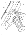
- FIG. 1 shows part of a motor vehicle 2.
- FIG. 1 shows one Front apron 4 and a bumper construction 6 of a passenger car.
- the bumper structure 6 has a bumper cover 8, a bumper 10 and a bending beam 12, which by means of a bolt 14 on the Bumper 10 is connected.
- the bumper cover 8 is typical made of a plastic material.
- the bumper cover 8 has some elasticity, and it is also a certain distance 16 from the bending beam 12 arranged so that the bumper cover 8 in the event of collisions is able to collision energy at extremely low speed convert into deformation energy of the bumper cover 8.
- the Bumper cover 8 is resilient and takes after such Impact back to its original shape at slow speed on.
- the bumper 10 is at its right end in the illustration in FIG. 1 connected to a supporting structure 18.
- the bumper 10 has one Absorber 20 and has two displaceable relative to each other in the direction of force Power transmission elements 22 and 24.
- the power transmission elements 22, 24 telescopically mounted.
- the Body-side power transmission element 24 is on its body-side End connected to the absorber 20 or forms an integral part of this.
- There is a locking device between the two power transmission elements 26 is provided as part of a decoupling device 28, the first and the second power transmission element 22, 24 is blocked relative to one another, so a collision force applied to the bending beam 12 on the absorber 20 and ultimately towards the supporting structure 18 of the vehicle body transfer.
- the bumper 10 is in the Longitudinal section shown.
- One also recognizes the one connected via a bolt 14 Bending beam 12 at the front, free end 32 of the bumper 10. You can also see the two slidably mounted relative to each other Power transmission elements 22 and 24 and the decoupling device 28 with the locking device 26 and the unlocking device 30.
- the decoupling device 28 or the blocking device 26 is at the same time as Absorber 20 formed.
- the first power transmission element 22 made of a machinable material, for example a plastic material or a relatively soft metal material. Its cheap, to manufacture the entire power transmission element 22 from this material. It it is also possible to produce only a part of it from the machinable material.
- the machinable part of the power transmission element 22 is as follows referred to as cutting element 34. Circumferentially around the elongated cutting element 34 arranged several cutting blades 36 are provided. Becomes a collision force over the bending beam 12 on the free end 32 of the Force transmission element 22 or applied to the cutting element 34, the cutting element 34 in the direction to the right in FIG.
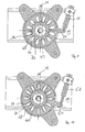
- FIG. 3 is a section through the bumper 10 along the line 3-3 shown in Fig. 2.
- the housing 40 of the decoupling device can be seen 28 or the absorber 20.
- the machining element can also be seen 34, around which a plurality of cutting knives 36 are arranged. Furthermore you can see that the cutting knife each several semicircular Have cutting edges 42 which fit into corresponding grooves 44 (see FIG. 2) of the cutting element 34 protrude.
- the cutting knives 36 are arranged in guides 46 in the housing 40.
- the cutting knives 36 are by means of pins 48 which are in control cams 50 which are in a Control cam 52 are formed in the radial direction, based on the elongated cutting element 34 is fixed.
- the control cam 52 has a lever 54 which by means of a Coil spring 56 is biased in the locked position. Grips the lever 54 also a pyrotechnic thrust element 58, which for the purpose of Unlocked by a controller (not shown) in the event of a collision in a relatively low speed range e.g. between 5 and 40 km / h triggers the pyrotechnic element 58. The pyrotechnic thrust element 58 then explosively pushes the lever 54 and rotates the control cam 52 in the representation of FIG. 3 in the counterclockwise direction.
- control curves 50 extend radially outwards arranged so that when the cam disc 52 is rotated counterclockwise the cutting knife 36 radially outwards via the pin 48 and pulled out of engagement with the cutting member 34.
- This situation is shown in FIG. In particular in FIG. 2, but also in the figures 3 to 5, you can also see a tension spring 60, the center of the two Power transmission elements 22, 24 is arranged tensioned and the two Power transmission elements 22, 24 against each other in a biased position holds.
- the unlocking device 38 is activated and activated the cutting knives 36 are disengaged from the cutting element 34, the tension spring 60 relaxes and pulls the force transmission element 22, which is connected to the bending beam 12, in the direction of the load-bearing Structure 18 of the vehicle body.
- a stop 62 prevents that in particular the bending beam 12 is essentially retracted without braking and vehicle parts, such as the radiator or add-on units of the engine or even the engine itself. It is convenient if the displacement path between the first and the second power transmission element is at least 50 to 100 mm. Looking at Fig.
- the bumper 8 may be convenient to cover the bumper 8 specially designed so that in the event of collisions in this speed spectrum an optimal protective effect for a pedestrian represents and absorbs its impact as gently as possible. It can also be cheap be, if instead of actively retracting the bending beam 12 or of the force transmission element 22 by the tension spring 60 is a purely passive Pushing back the force transmission element 22 and the bending beam 12 against the frictional forces. You may also be able to get a very targeted one predetermined force curve, for example by the provision of compression springs in place of the tension spring 60 or other resilient elements be, which delicately delays the impact of the pedestrian is effected. Basically it is possible to in place or in addition to the tension spring 60 other actuators, e.g. Electric motors, magnets, pneumatic or hydraulic actuators. You can also get a subdivision the movement path between the force transmission elements 22, Imagine 24, so that an active withdrawal only over a first part of the movement path and then the bending beam and that Power transmission element 22 may be pushed back against a predetermined counterforce be, etc
- FIGS. 7 to 11 An alternative embodiment is described below with reference to FIGS. 7 to 11 shown for a bumper. It should be noted that same Reference signs the same or corresponding elements in the individual views affect. It should be particularly noted that with regard to information given in one embodiment generally also applies to the other embodiment Can be used, unless the special design this embodiment allows the transfer of these features and properties Not.
- FIG. 7 shows a perspective view of a bumper 10 according to FIG present invention.
- Fig. 8 is a longitudinal section through the bumper 10.
- the basic structure is similar to the bumper 10 of the first embodiment.
- the decoupling device 28 also has a housing 40. In the housing there is also a beveled groove 38 provided through which the chip of the absorber 20 can escape.
- this chip ejection groove 38 is only in the area of Knife provided.
- leadership projections 64 provided that a correct arrival of the transfer of the Ensure power transmission element 22 in the absorber 20.
- the cutting knives 36 are rotatably mounted about axes 66 and a support 68 in the direction of force behind the chipping knives 36 is provided , which ensures that the cutting knife 36 is not pulling the spring 60 fold back.
- the support 68 is designed in the manner of a backdrop disc.
- recesses 70 are alternately provided with holding projections 72.
- the holding projections 72 support the foldable cutting knife 36 and hold it in the locked position. Will the Unlocking device 30 and thus the pyrotechnic thrust element 58 activated, thus the support disc 78 in the embodiment shown in FIG.
- a chipper knife stop 74 is provided to prevent the chipper knife 36 Bend or damage parts of the housing 40. It can be favorable, the support plate 68 and / or the cutting knife 36 for example by chamfering the corresponding edges in such a way that by turning the support disk 68 back into the cutting knife 36 the position shown in Fig. 8 can be moved back after the Power transmission elements 22, 24 are brought into their starting position.
- the reset of the Bumper 10 can be done relatively easily by the power transmission elements 22, 24 are brought into their starting position and the cutting knife be engaged again so that they are the power transmission elements Lock 22 and 24 in the starting position.
- the stop 62 can serve here as a guide together with a groove 44, so that is ensured is that the cutting knife 36 in the corresponding grooves 44 is correct can be positioned.
- a reset will be made in the workshop a new pyrotechnic thrust element 58 can also be used regularly.
- a mechanism by means of which can be reset by the vehicle user so that a Workshop stay is not required.
- another instead of the pyrotechnic thrust element 58 is reusable Actuator with electromagnetic, motor, pneumatic, hydraulic etc., drive is provided.
- the usage such alternative actuators instead of the pyrotechnic thrust element 58 is not tied to the presence of a reset mechanism.
- the cutting knife 36 together with the cutting element 34 together form an absorber 20 similarly the cutting knife can only be used as locking elements, the corresponding ones Grooves 44 cooperate in the power transmission element 22. That is special cheap if parts of the bodywork are specifically designed as absorbers 20 are formed or if a special, separate absorber 20 is used shall be.
Abstract
Description
Die vorliegende Erfindung betrifft Stoßfänger zum Anschluss an eine Kraftfahrzeugkarosserie und zum Übertragen einer Kraft im Wesentlichen in der Richtung der Längsachse des Fahrzeugs, einer Kraft, wie sie beispielsweise bei einer Kollision des Fahrzeugs auftritt. Die Erfindung betrifft insbesondere Stoßfänger, die für eine Kollision mit Fußgängern oder Radfahrern, etc. optimiert sind.The present invention relates to bumpers for connection to a motor vehicle body and for transmitting a force substantially in the direction the longitudinal axis of the vehicle, a force such as that of a Collision of the vehicle occurs. The invention relates in particular to bumpers, which is optimized for a collision with pedestrians or cyclists, etc. are.
Aktuelle Kraftfahrzeuge und insbesondere Personenkraftwagen haben eine an der tragenden Struktur der Kraftfahrzeugkarosserie angeschlossene Stoßfängerkonstruktion zum Abbau und Übertragen von Kollisionskräften auf die tragende Struktur der Fahrzeugkarosserie. Typischerweise umfasst bei modernen Fahrzeugen eine derartige Stoßfängerkonstruktion von außen nach innen betrachtet eine Stoßfängerabdeckung, typischerweise aus einem Kunststoffmaterial mit einer Gesichtsseite, die nach außen exponiert ist und von dem Betrachter als der eigentliche Stoßfänger verstanden wird. Diese Stoßfängerabdeckung ist typischerweise derart ausgelegt, dass sie Kollisionen im sehr langsamen Geschwindigkeitsbereich beispielsweise bis typischerweise 5, 8 oder 10 km/h ohne eine wesentliche Beschädigung aufnehmen kann. Für Kollisionen bei höherer Geschwindigkeit ist innen von dieser Stoßfängerabdeckung ein Biegebalken oder Stoßfängerträger vorgesehen, der an zwei oder mehreren Stellen von je einem Stoßfänger gegen die Kraftfahrzeugkarosserie abgestützt ist. In derartigen Stoßfängern ist typischerweise ein Absorber vorgesehen, der ab einer bestimmten Kollisionsgeschwindigkeit Kollisionsenergie abbaut und vernichtet, beispielsweise indem Verformungsarbeit durch Verbiegen, Umstülpen, etc. geleistet wird. Ein anderes Absorberprinzip basiert auf dem Prinzip des Abbaus der Kollisionsenergie durch das Leisten von Zerspanungsarbeit. Dabei befinden sich Zerspanmesser mit einem Zerspanelement in Eingriff und zerspanen bei einer Relativbewegung zwischen dem Zerspanelement und den Zerspanmessern das Zerspanelement. Ein derartiger Absorber hat einen sehr hohen Wirkungsgrad, und durch eine optimale Materialpaarung zwischen den Zerspanmessern und dem Zerspanelement lassen sich sehr gezielt Kraftverläufe über den Absorberweg einstellen und optimieren. Typischerweise sind die Zerspanmesser an der tragenden Struktur der Kraftfahrzeugkarosserie angeschlossen, während das Zerspanelement ein im Wesentlichen längliches Element ist, das an dem Biegebalken angeschlossen ist und im Falle einer Kollision gegen die Zerspanmesser verschoben wird.Current motor vehicles and especially passenger cars have one on bumper structure connected to the load-bearing structure of the motor vehicle body to reduce and transfer collision forces to the load-bearing Structure of the vehicle body. Typically includes in modern Vehicles considered such a bumper construction from the outside in a bumper cover, typically made of a plastic material with a face that is exposed to the outside and by the viewer is understood as the actual bumper. This bumper cover is typically designed to cause very slow collisions Speed range for example up to typically 5, 8 or 10 km / h without significant damage. For collisions at higher speed, there is a bending beam inside of this bumper cover or bumper support provided at two or more locations is supported by a bumper against the motor vehicle body. In Such bumpers are typically provided with an absorber certain collision speed breaks down and destroys collision energy, for example by deforming by bending, turning inside out, etc. is performed. Another absorber principle is based on the principle of Reduction of the collision energy by performing cutting work. there are cutting knives with a cutting element in engagement and cutting with a relative movement between the cutting element and the Cutting knives the cutting element. Such an absorber has a lot high efficiency, and through an optimal material pairing between the Cutting knives and the cutting element can be very targeted force profiles adjust and optimize via the absorber path. Typically they are Cutting knife connected to the load-bearing structure of the vehicle body, while the cutting element is a substantially elongated element is connected to the bending beam and in the event of a collision is moved against the cutting knife.
Es wurde bereits erwähnt, dass die Stoßfängerabdeckung in sehr niedrigen Geschwindigkeitsbereichen im Wesentlichen die Kollisionsenergie aufnimmt und abbaut. Die Stoßfängerabdeckung ist relativ weich, so dass es in diesem Geschwindigkeitsbereich bei Kollisionen mit ungeschützten Personen, wie beispielsweise Fußgängern, Radfahrern, etc., nicht zu erheblichen Verletzungen als unmittelbare Folge des Aufpralls kommt. Anders sieht die typische Unfallcharakteristik bei höheren Aufprallgeschwindigkeiten bis beispielsweise 40 km/h aus. In diesem Geschwindigkeitsbereich wirkt der Biegebalken wie ein starrer Rammbock und verursacht erhebliche Verletzungen insbesondere im Bereich der unteren Extremitäten bei den genannten Personengruppen, die der Einfachheit halber nachfolgend als "Fußgänger" bezeichnet werden.It has already been mentioned that the bumper cover is very low Speed ranges essentially absorbs the collision energy and breaks down. The bumper cover is relatively soft, so it's in this Speed range for collisions with unprotected people, such as Pedestrians, cyclists, etc., not considered to be significant injuries immediate consequence of the impact comes. The typical accident characteristics are different at higher impact speeds up to 40 km / h, for example out. In this speed range, the bending beam looks like a rigid one Battering ram and causes significant injuries especially in the area of the lower extremities in the named groups of people, that of simplicity are referred to below as "pedestrians".
Es ist deshalb die Aufgabe der vorliegenden Erfindung, einen Stoßfänger bereitzustellen, der das Verletzungsrisiko von Fußgängern bei Kollisionen mit Kraftfahrzeugen verringert.It is therefore the object of the present invention to provide a bumper the risk of injury to pedestrians in collisions with Motor vehicles reduced.
Erfindungsgemäß wird diese Aufgabe gelöst durch einen Stoßfänger zum Anschließen an eine tragende Struktur einer Kraftfahrzeugkarosserie und zum Übertragen einer Kraft im Wesentlichen in der Richtung der Längsachse des Fahrzeugs, aufweisend eine Entkopplungseinrichtung mit einem ersten und einem zweiten in Kraftübertragungsrichtung relativ zueinander verlagerbaren Kraftübertragungselement, einer Sperreinrichtung, die das erste und das zweite Kraftübertragungselement relativ zueinander versperrt, und eine an der Sperreinrichtung angeschlossenen Entsperreinrichtung, welche die Versperrung zwischen dem ersten und dem zweiten Kraftübertragungselement aufhebt und eine Relativbewegung zwischen beiden zulässt.According to the invention, this object is achieved by a bumper for connection to a supporting structure of a motor vehicle body and Transmitting a force substantially in the direction of the longitudinal axis of the Vehicle, comprising a decoupling device with a first and a second displaceable relative to each other in the direction of power transmission Power transmission element, a locking device that the first and the second Power transmission element blocked relative to each other, and one on the locking device connected unlocking device, which the blocking between the first and the second power transmission element and allows a relative movement between the two.
Wie bereits erwähnt, handelt es sich bei der Kraft im Wesentlichen um eine bei einer Kollision auftretenden Kollisionskraft. Diese ist typischerweise bei dem Aufprall auf einen vorderen Stoßfänger in Längsrichtung des Fahrzeugs gerichtet, wobei eine mehr oder minder starke Lateralkomponente vorhanden sein kann. Es mag Situationen geben, in denen derartige Stoßfänger seitlich am Fahrzeug vorgesehen sind, so dass die Hauptkraftrichtung eher rechtwinklig zur Längsachse vorgesehen ist. Die Entkopplungseinrichtung erfüllt den Zweck, in bestimmten Situationen die Kraftübertragung von dem Stoßfänger auf die tragende Struktur der Kraftfahrzeugkarosserie aufzuheben. Bei der vorangehend geschilderten Stoßfängerkonstruktion moderner Kraftfahrzeuge hat das zur Folge, dass über den Biegebalken im Wesentlichen keine Kraft auf den Fußgänger übertrage wird. Vielmehr wird die Kollisionsenergie im Wesentlichen über die relativ weiche Stoßfängerabdeckung aufgenommen und übertragen. Es ist einsichtig, dass das Verletzungsrisiko für den Fußgänger auf diese Weise deutlich minimiert ist. Die Entkopplungseinrichtung ist grundsätzlich so aufgebaut, dass Kollisionskräfte, die an dem vorderen oder karosseriefernen, freien Ende des Stoßfänders aufgebracht werden, mehr oder weniger gedämpft auf die tragende Struktur der Kraftfahrzeugkarosserie übertragen werden. Die Dämpfung kann beispielsweise durch einen Absorber erfolgen, der in den Stoßfänger integriert sein kann. Die Entkopplungseinrichtung weist zu diesem Zweck eine Sperreinrichtung auf, die ein erstes Kraftübertragungselement und ein zweites relativ zu dem ersten Kraftübertragungselement verlagerbares Kraftübertragungselement relativ zueinander versperrt, so dass die Kraftübertragung - gedämpft oder ungedämpft - erfolgen kann.As previously mentioned, the force is essentially a a collision force occurring. This is typically with the Impact on a front bumper in the longitudinal direction of the vehicle, with a more or less strong lateral component can. There may be situations in which such bumpers are on the side Vehicle are provided so that the main direction of force is rather perpendicular to Longitudinal axis is provided. The decoupling device serves the purpose in certain situations, the power transmission from the bumper to the load-bearing To cancel the structure of the vehicle body. In the previous described bumper construction of modern motor vehicles As a result, there is essentially no force on the pedestrian over the bending beam is transmitted. Rather, the collision energy is essentially recorded and transmitted via the relatively soft bumper cover. It is clear that the risk of injury to the pedestrian in this way is significantly minimized. The decoupling device is basically constructed that collision forces that are on the front or away from the body, free Be applied at the end of the bumper, more or less damped the supporting structure of the motor vehicle body are transferred. The Damping can be done for example by an absorber in the Bumpers can be integrated. The decoupling device points to this Purpose of a locking device that a first power transmission element and a second displaceable relative to the first power transmission element Power transmission element blocked relative to each other, so that the power transmission - steamed or undamped - can be done.
Die Versperrung der Sperreinrichtung kann durch eine Entsperreinrichtung aufgehoben werden. Die Entsperreinrichtung kann mit Sensoren zusammenwirken, beispielsweise einem Geschwindigkeitssensor, einem oder mehreren Kollisionssensoren etc. Vergleichbare Sensorsysteme sind bei aktiven Fronthaubensystemen bereits im Einsatz, die im Falle der Kollision des Fahrzeugs mit einem Fußgänger die Fronhaube anheben, um bei einem Sekundäraufprall des Fußgängers auf das Fahrzeug die Verletzungen des Fußgängers zu reduzieren. Diese Sensoren können auch für die Aktivierung des Stoßfängers herangezogen werden, wobei die Geschwindigkeitsbereiche, bei denen eine Aktivierung erfolgt, oder andere Kriterien, anders als bei den aktiven Fronthabensystemen, ggf. auch in gleicher Weise gewählt sein können.The locking device can be blocked by an unlocking device To get picked up. The unlocking device can interact with sensors for example a speed sensor, one or more Collision sensors etc. Comparable sensor systems are with active bonnet systems already in use in the event of a collision with the vehicle lift the front hood of a pedestrian in order to avoid a secondary impact of the Pedestrian on the vehicle to reduce pedestrian injuries. These sensors can also be used to activate the bumper be, the speed ranges at which activation done, or other criteria, unlike the active front systems, can optionally also be selected in the same way.
Es ist günstig, die Entkopplungseinrichtung derart an das Sensorsystem anzuschließen, dass es zu einer Auslösung der Entsperreinrichtung und somit zu einer Freigabe der Relativbewegung zwischen dem ersten und dem zweiten Kraftübertragungselement nur in einem gewissen vorgegebenen Geschwindigkeitsfenster kommt. Oberhalb einer bestimmten Geschwindigkeit sind einerseits die Aufprallfolgen für den Fußgänger praktisch unabhängig davon, ob der Stoßfänger nachgibt oder nicht. Andererseits muss bei höheren Aufprallgeschwindigkeiten mit Blick auf den Schutz der Fahrzeuginsassen die vorgegebene Absorptionscharakteristik des Stoßfängers zum Einsatz kommen, zumal Sensorsysteme nicht in der Lage sind, zwischen einem Aufprall auf einen Fußgänger und dem Aufprall auf eine Wand zu unterscheiden. Die Geschwindigkeitsbereiche, bei denen die Entkopplungseinrichtung den Kraftweg zwischen dem karosseriefernen Ende des Stoßfängers und der Karosserie entkoppelt bzw. beibehält, können die gleichen Geschwindigkeitsbereiche sein, wie sie für eine entsprechende Sicherheits-Fronthaube implementiert sind. Es können jedoch andere Geschwindigkeitsbereiche je nach der Konstruktion des Fahrzeugs bzw. des Stoßfängers bzw. der Stoßfängerkonstruktion zum Einsatz kommen.It is favorable to connect the decoupling device to the sensor system in such a way that there is a triggering of the unlocking device and thus to a Release of the relative movement between the first and the second Power transmission element only in a certain predetermined speed window comes. Above a certain speed are on the one hand the impact consequences for the pedestrian practically regardless of whether the bumper gives way or not. On the other hand, at higher impact speeds with a view to protecting the occupants of the vehicle Absorption characteristics of the bumper are used, especially since Sensor systems are unable to crash between a pedestrian and distinguish the impact on a wall. The speed ranges, where the decoupling device the force path between decoupled the far end of the bumper and the body or maintains, can be the same speed ranges as for a corresponding safety hood has been implemented. However, it can other speed ranges depending on the construction of the vehicle or the bumper or the bumper construction are used.
Ein wesentlicher Punkt bei der Konstruktion eines derartigen Stoßfängers ist es, die Auslösezeiten bis zu einer kompletten Entkopplung des Kraftwegs ausreichend kurz auszulegen. Hier sind Zeiträume bis zur Entkopplung von 30 ms und weniger erwünscht.An essential point in the construction of such a bumper is the tripping times up to a complete decoupling of the force path are sufficient to interpret briefly. Here are periods up to 30 ms decoupling and less desirable.
Vorzugsweise weist der Stoßfänger eine Rückzieheinrichtung auf, die zwischen dem ersten und dem zweiten Kraftübertragungselement derart angeschlossen ist, dass sie nach dem Aufheben der Sperrung zwischen dem ersten und dem zweiten Kraftübertragungselement aktiv eine Relativbewegung zwischen beiden bewirkt. Ohne die Verwendung einer Rückzieheinrichtung wird der Stoßfänger lediglich "weich" und kann bei dem Aufprall mit dem Fußgänger zurückgeschoben werden. Bei der Verwendung einer Rückzieheinrichtuhg wird der Stoßfänger aktiv eine gewisse Strecke, beispielsweise einige wenige cm bis zu 10 cm und mehr zurückgezogen, so dass ein wesentlicher Teil der Aufprallenergie im Verlauf der Verformung einer Stoßfängerabdeckung aufgenommen werden kann. Andererseits ist es auch möglich, auf die Rückzieheinrichtung zu verzichten und den Stoßfänger selbst mit einer elastischen Dämpfungseinrichtung auszubilden, die nach der Entkopplung des direkten Kraftwegs zur Karosserie eine elastisch nachgiebige Kraft dem Aufprall des Fußgängers entgegensetzt. Eine derartige Dämpfungseinrichtung kann beispielsweise eine Feder oder ein elastisches Material, beispielsweise ein Schaummaterial, aufweisen.The bumper preferably has a retraction device, which between connected to the first and the second power transmission element in this way is that after the lock is released between the first and the second power transmission element actively a relative movement between the two causes. Without using a retractor, the bumper becomes only "soft" and can be pushed back on impact with the pedestrian become. When using a retractor, the bumper is active a certain distance, for example a few cm up to 10 cm and withdrawn more so that a significant portion of the impact energy in the Course of deformation of a bumper cover can be included can. On the other hand, it is also possible to dispense with the retraction device and the bumper itself with an elastic damping device train that after decoupling the direct power path to the body an elastic, resilient force opposes the impact of the pedestrian. Such a damping device can for example be a spring or a have elastic material, for example a foam material.
Vorzugsweise weist die Rückzieheinrichtung eine vorgespannte Feder auf. Besonders bevorzugt ist eine vorgespannte Schraubenfeder, eine derartige Feder lässt sich relativ einfach und kostengünstig herstellen und ist leicht zu installieren.The retraction device preferably has a prestressed spring. Especially a prestressed coil spring is preferred, such a spring is relatively simple and inexpensive to manufacture and is easy to install.
Vorzugsweise weist der Stoßfänger einen Absorber auf, wobei es besonders bevorzugt ist, die Entkopplungseinrichtung als einen Bestandteil des Absorbers auszubilden. Bei einer derartigen integrierten Konstruktion lassen sich Bauraum und Herstellungsaufwand verringern.The bumper preferably has an absorber, with it being particularly is preferred, the decoupling device as a component of the absorber train. With such an integrated construction, there is space and reduce manufacturing costs.
Vorzugsweise arbeitet der Absorber nach dem vorangehend bereits erwähnten Zerspanungsprinzip und weist vorzugsweise ein Zerspanelement und ein mit diesem im Eingriff befindliches Zerspanmesser auf. Es ist besonders bevorzugt, wenn das Zerspanelement ein Bestandteil des zweiten Kraftübertragungselements ist und das Zerspanmesser ein-Bestandteil der Sperreinrichtung ist. Es ist besonders günstig, gerade bei Absorbern, die nach dem Zerspanprinzip arbeiten, eine derartige Entkopplungseinrichtung vorzusehen, da derartige Einrichtungen häufig einen im Wesentlichen rechtwinkligen Kraft-Wegverlauf über den Absorberweg aufweisen, so dass bei dem Anprall des Fußgängers auf den Stoßfänger erst eine Schwellenwertkraft überschritten werden muss, bevor der Absorber zusammengedrückt wird und sich der Stoßfänger verlagert. Dieser Schwellenwert ist typischerweise relativ hoch. Vorzugsweise ist ein längliches erstes Kraftübertragungselement vorgesehen, um welches herum das zweite Kraftübertragungselement angeordnet ist, so dass zwischen den beiden Elementen vorzugsweise eine Führung ausgebildet ist. Es ist besonders günstig, bei einem nach dem Zerspanprinzip arbeitenden Absorber das erste Kraftübertragungselement in der Art eines länglichen Zerspanelements auszubilden, und es ist weiter bevorzugt, um dieses längliche Zerspanelement umfangsmäßig darum herum angeordnete Zerspanmesser vorzusehen, die derart an der Sperreinrichtung angeschlossen sind, dass sie sich normal in einer Eingriffsposition mit dem länglichen Zerspanelement befindet und damit die Sperreinrichtung bildet und so an eine Entsprerreinrichtung angeschlossen sind, dass sie bei einer Auslösung aus diesem Sperreingriff gebracht werden. Vorzugsweise ist das bzw. sind die Zerspanmesser in einer Führung rechtwinklig zur Längsachse des Zerspanelements verlagerbar angeordnet und an die Entsperreinrichtung angeschlossen. Die Entsperreinrichtung kann so ausgebildet sein, dass sie die Zerspanmesser aus der Eingriffsposition in eine Position verlagert, in der die Versperrung zwischen dem ersten und dem zweiten Kraftübertragungselement aufgehoben ist und eine Relativbewegung zwischen beiden zugelassen ist.The absorber preferably operates according to the one already mentioned above Machining principle and preferably has a machining element and a this cutting tool in engagement. It is particularly preferred if the cutting element is part of the second power transmission element and the cutting knife is a component of the locking device. It is particularly cheap, especially for absorbers that work according to the machining principle, to provide such a decoupling device, since such devices often a substantially rectangular force-displacement curve have the absorber path, so that when the pedestrian collides with the A threshold force must first be exceeded before the bumper Absorber is compressed and the bumper moves. This The threshold is typically relatively high. Preferably an elongated one provided first power transmission element, around which the second Power transmission element is arranged so that between the two elements preferably a guide is formed. It is particularly convenient in the case of an absorber working according to the machining principle, the first force transmission element in the manner of an elongated cutting element, and it is further preferred to circumferentially encircle this elongated cutting element to provide arranged cutting knives that so on the Locking devices are connected so that they are normally in an engaged position with the elongated cutting element and thus the locking device forms and are connected to an expander that they be brought out of this lockout intervention when triggered. Preferably is that or the cutting knives in a guide perpendicular to the longitudinal axis of the cutting element arranged displaceably and to the unlocking device connected. The unlocking device can be designed such that they move the cutting knife from the engaged position to a position in which the blockage between the first and the second power transmission element is canceled and a relative movement between the two is permitted is.
Vorzugsweise weist die Entsperreinrichtung eine Steuerkurvenscheibe auf, in der mit den Zerspanmessern zusammenwirkende Steuerkurven vorgesehen sind, die derart ausgebildet sind, das ein Verlagern der Steuerkurvenscheibe die Zerspanmesser aus einer Sperrposition in eine Entsperrposition verlagern kann und umgekehrt. Die Zerspanmesser können beispielsweise Stifte aufweisen, die in die Steuerkurven in der Steuerkurvenscheibe eingreifen und damit durch eine Verlagerung, beispielsweise eine Rotation der Steuerkurvenscheibe, außer Eingriff gezogen werden können. Bei einer derartigen Konstruktion kann die Steuerkurvenscheibe vorzugsweise ein Teil der Führung für das bzw. die Zerspanmesser bilden. Es kann günstig sein, die Steuerkurvenscheibe um die Längsachse des länglichen Zerspanelements drehbar anzuordnen. Bei einer derartigen Konstruktion können die einzelnen Steuerkurven an identischen Radialpositionen vorgesehen sein. Auf diese Weise lässt sich eine besonders einfache Herstellung der Steuerkurvenscheibe realisieren. Außerdem kann die Steuerkurvenscheibe einer derartigen Konstruktion relativ einfach in einer Rotationsführung angeordnet sein. Generell ist es günstig, eine Führung für die Steuerkurvenscheibe vorzusehen.The unlocking device preferably has a control cam, in the control curves interacting with the cutting knives are, which are designed such that a displacement of the control cam Can move the cutting knife from a locked position to an unlocked position and vice versa. The cutting knife can, for example, have pins that engage in the control cams in the control cam disc and thus by a Displacement, for example a rotation of the cam, except Can be pulled. With such a construction, the Control cam preferably part of the guide for the or the cutting knife form. It may be convenient to move the cam disc around the To arrange the longitudinal axis of the elongated cutting element rotatably. At a Such a construction allows the individual control cams to be in identical radial positions be provided. In this way, a particularly simple one Realize the manufacture of the control cam. In addition, the Control cam of such a construction relatively simple in a rotation guide be arranged. Generally it is convenient to have a guide for that Control cam to be provided.
Alternativ zu der Anordnung der Zerspanmesser verlagerbar in einer Führung rechtwinklig zur Längsachse des Zerspanelements kann es bevorzugt sein, ein oder mehrere Zerspanmesser vorzusehen, die in einer Aufnahme festgelegt sind und von einer Abstützung in der Sperrposition gegen die Kraftübertragungsrichtung gehälten sind. Dabei ist es bevorzugt, die Entsperreinrichtung derart an die Abstützung anzuschließen, dass eine Betätigung der Entsperreinrichtung die Abstützung derart verlagert, dass das bzw. die Zerspanmesser in Kraftübertragungsrichtung freigegeben sind. Dabei kann es günstig sein, die Zerspanmesser um eine Achse drehbar anzuordnen, so das nach der Betätigung der Entsperreinrichtung und nach dem Entfernen der Abstützung die Zerspanmesser aus dem Eingriff mit dem Zerspanelement um die Achse verdreht und außer Eingriff gebracht werden.As an alternative to the arrangement of the cutting knife, it can be moved in a guide at right angles to the longitudinal axis of the machining element, it can be preferred to use a or to provide several cutting knives, which are fixed in one holder are and from a support in the locked position against the direction of force transmission are held. It is preferred to use the unlocking device to be connected to the support such that actuation of the unlocking device the support is shifted such that the cutting knife (s) in Power transmission direction are released. It may be convenient that Arrange the cutting knife so that it can be rotated around an axis, after actuation the unlocking device and after removing the support Cutting knife rotated around the axis from engagement with the cutting element and disengaged.
Vorzugsweise ist ein Anschlag zwischen dem ersten und dem zweiten Kraftübertragungselement vorgesehen, der nach der Freigabe die Relativbewegung zwischen den beiden Elementen nach einer gewissen vorgegebenen Strecke beendet. Der Anschlag ist besonders dann günstig, wenn eine aktive Rückzieheinrichtung vorgesehen ist, um zu verhindern, dass die Rückbewegung des Stoßfängers von dem Motor, von Hilfsaggregaten oder Anbauteilen gebremst wird und Schäden verursacht.There is preferably a stop between the first and the second Power transmission element is provided, which after the release of the relative movement between the two elements according to a certain predetermined Route ended. The attack is particularly favorable when there is an active one Retractor is provided to prevent the retraction the bumper is braked by the engine, auxiliary units or attachments and causes damage.
Vorzugsweise weist die Entsperreinrichtung ein pyrotechnisches Schubelement auf. Pyrotechnische Schubelemente sind in der Lage, relativ hohe Kräfte innerhalb extrem kurzer Zeit bereitzustellen, so dass mit pyrotechnischen Schubelementen ausgestattete Entsperreinrichtung eine relativ hohe Auslösegeschwindigkeit bzw. kurze Auslösezeit realisieren können. Das pyrotechnische Schubelement kenn beispielsweise über eine Schräge derart mit dem ersten oder dem zweiten Kraftübertragungselement gekoppelt sein, dass es zusätzlich die Relativbewegung zwischen den beiden Elementen nach der Entsperrung bewirkt oder unterstützt. The unlocking device preferably has a pyrotechnic thrust element on. Pyrotechnic thrust elements are able to withstand relatively high forces extremely short time, so that with pyrotechnic thrust elements equipped unlocking device a relatively high release speed or short tripping time. The pyrotechnic Thrust element knows, for example, via a slope in such a way with the first or be coupled to the second power transmission element, that it additionally the relative movement between the two elements after unlocking causes or supports.
Die Erfindung betrifft ferner ein Kraftfahrzeug, aufweisend einen Stoßfänger gemäß der vorliegenden Erfindung. Ein derartiger Stoßfänger kann beispielsweise auch in der Art eine pufferartigen Elements alleine an dem Fahrzeug vorgesehen sein. Vorzugsweise weist das Kraftfahrzeug jedoch mindestens zwei Stoßfänger und einen mit dem karosseriefernen, freien Ende des Stoßfängers verbundenen Biegebalken auf. Der Biegebalken kann selbst in der Art einer konventionellen Stoßstange exponiert sein. Es ist bevorzugt, wenn eine Stoßfängerabdeckung außerhalb des Stoßfängers bzw. außerhalb des Biegebalkens vorgesehen ist.The invention further relates to a motor vehicle, having a bumper according to the present invention. Such a bumper can, for example also like a buffer-like element on the vehicle alone be provided. However, the motor vehicle preferably has at least two bumpers and one with the free end of the bumper away from the body connected bending beam. The bending beam can even be of the type exposed to a conventional bumper. It is preferred if one Bumper cover outside the bumper or outside the bending beam is provided.
Die Erfindung betrifft ferner eine Stoßfängerbaugruppe zum Einbau in ein Kraftfahrzeug, aufweisend mindestens zwei erfindungsgemäße Stoßfänger, einen Biegebalken zum Anschluss an die karosseriefernen, freien Enden der Stoßfänger und eine Stoßfängerabdeckung. The invention further relates to a bumper assembly for installation in a Motor vehicle, having at least two bumpers according to the invention, one Bending beam for connection to the free ends of the Bumper and a bumper cover.
Die Erfindung und Ausgestaltungen der Erfindung werden nachfolgend an Hand eines zeichnerisch dargestellten Ausführungsbeispiels näher erläutert. Es zeigen:
- Fig. 1
- eine schematische Schnittansicht durch den Stoßfängerbereich eines Kraftfahrzeugs;
- Fig. 2
- einen Längschnitt durch einen erfindungsgemäßen Stoßfänger gemäß einer ersten Ausführungsform;
- Fig. 3
- einen Schnitt durch den Stoßfänger gemäß Fig. 2, der an den Linien 3-3 genommen ist;
- Fig. 4
- einen Schnitt durch den Stoßfänger der Fig. 2, der an der Linie 4-4 genommen ist;
- Fig. 5
- einen Schnitt ähnlich dem von Fig. 3, bei dem die Zerspanmesser außer Eingriff sind;
- Fig. 6
- einen Längsschnitt durch den Stoßfänger gemäß Fig. 2 im zurückgezogenen Zustand;
- Fig. 7
- eine perspektivische Ansicht eines Stoßfängers gemäß einer zweiten Ausführungsform;
- Fig. 8
- einen Längsschnitt durch den Stoßfänger gemäß der zweiten Ausführungsform;
- Fig. 9
- einen Schnitt durch den Stoßfänger der zweiten Ausführungsform, der an der Linie 9-9 von Fig. 8 genommen ist;
- Fig. 10
- einen Schnitt ähnlich zu dem von Fig. 9, der ebenfalls an der Linie 9-9 genommen ist; und
- Fig. 11
- einen Schnitt ähnlich zu dem von Fig. 8, der den Stoßfänger in der zurückgezogenen Position zeigt.
- Fig. 1
- a schematic sectional view through the bumper area of a motor vehicle;
- Fig. 2
- a longitudinal section through a bumper according to the invention according to a first embodiment;
- Fig. 3
- a section through the bumper of Figure 2, which is taken on lines 3-3.
- Fig. 4
- a section through the bumper of Figure 2, which is taken on the line 4-4.
- Fig. 5
- a section similar to that of Figure 3, in which the cutting knives are disengaged.
- Fig. 6
- a longitudinal section through the bumper of Figure 2 in the retracted state.
- Fig. 7
- a perspective view of a bumper according to a second embodiment;
- Fig. 8
- a longitudinal section through the bumper according to the second embodiment;
- Fig. 9
- a section through the bumper of the second embodiment, which is taken on the line 9-9 of Fig. 8;
- Fig. 10
- a section similar to that of Figure 9, which is also taken on line 9-9. and
- Fig. 11
- a section similar to that of Fig. 8, showing the bumper in the retracted position.
Fig. 1 zeigt einen Teil eines Kraftfahrzeugs 2. Insbesondere zeigt Fig. 1 eine
Frontschürze 4 und eine Stoßfängerkonstruktion 6 eines Personenwagens.1 shows part of a motor vehicle 2. In particular, FIG. 1 shows one
Die Stoßfängerkonstruktion 6 weist eine Stoßfängerabdeckung 8, einen Stoßfänger
10 sowie einen Biegebalken 12 auf, der mittels eines Bolzens 14 an dem
Stoßfänger 10 angeschlossen ist. Die Stoßfängerabdeckung 8 ist typischerweise
aus einem Kunststoffmaterial hergestellt. Die Stoßfängerabdeckung 8 hat
eine gewisse Elastizität, und sie ist ferner mit einem gewissen Abstand 16 von
dem Biegebalken 12 angeordnet, so dass die Stoßfängerabdeckung 8 bei Kollisionen
bei extrem niedriger Geschwindigkeit in der Lage ist, die Kollisionsenergie
in Verformungsenergie der Stoßfängerabdeckung 8 umzuwandeln. Die
Stoßfängerabdeckung 8 ist elastisch nachgiebig und nimmt nach einem derartigen
Aufprall bei langsamer Geschwindigkeit wieder ihre ursprüngliche Form
an. Der Stoßfänger 10 ist an seinem rechten Ende in der Darstellung der Fig. 1
an einer tragenden Struktur 18 angeschlossen. Der Stoßfänger 10 weist einen
Absorber 20 auf und besitzt zwei in Kraftrichtung relativ zueinander verlagerbare
Kraftübertragungselemente 22 und 24. Insbesondere sind die Kraftübertragungselemente
22, 24 teleskopisch ineinander verschiebbar gelagert. Das
karosserieseitige Kraftübertragungselement 24 ist an seinem karosserieseitigen
Ende an den Absorber 20 angeschlossen bzw. bildet ein integrales Teil von
diesem. Zwischen den beiden Kraftübertragungselementen ist eine Sperreinrichtung
26 als Teil einer Entkopplungseinrichtung 28 vorgesehen, die das erste
und das zweite Kraftübertragungselement 22, 24 relativ zueinander versperrt,
um so eine auf den Biegebalken 12 aufgebrachte Kollisionskraft auf den Absorber
20 und letztlich auf die tragende Struktur 18 der Fahrzeugkarosserie zu
übertragen.The bumper structure 6 has a
In der "Blackbox" der Entkopplungseinrichtung 28 ist ferner eine Entsperreinrichtung
20 vorgesehen, welche die Versperrung zwischen dem ersten und
dem zweiten Kraftübertragungselement aufheben kann und eine Relativbewegung
zwischen beiden zulassen kann. In der Fig. 2 ist der Stoßfänger 10 im
Längsschnitt gezeigt. Man erkennt ferner den über einen Bolzen 14 angeschlossenen
Biegebalken 12 an dem vorderen, freien Ende 32 des Stoßfängers
10. Man erkennt ferner die beiden relativ zueinander verschiebbar gelagerten
Kraftübertragungselemente 22 und 24 sowie die Entkopplungseinrichtung 28
mit der Sperreinrichtung 26 und der Entriegelungseinrichtung 30.In the "black box" of the
Die Entkopplungseinrichtung 28 bzw. die Sperreinrichtung 26 ist gleichzeitig als
Absorber 20 ausgebildet. Zu diesem Zweck ist das erste Kraftübertragungselement
22 aus einem zerspanbaren Material, beispielsweise einem Kunststoffmaterial
oder einem relativ weichen Metallmaterial hergestellt. Es ist günstig,
das gesamte Kraftübertragungselement 22 aus diesem Material herzustellen. Es
ist auch möglich, nur einen Teil davon aus dem zerspanbaren Material herzustellen.
Der zerspanbare Teil des Kraftübertragungselements 22 wird nachfolgend
als Zerspanelement 34 bezeichnet. Umfangsmäßig um das längliche Zerspanelement
34 angeordnet sind mehrere Zerspanmesser 36 vorgesehen. Wird
eine Kollisionskraft über den Biegebalken 12 auf das freie Ende 32 des
Kraftübertragungselements 22 bzw. auf das Zerspanelement 34 aufgebracht,
wird das Zerspanelement 34 in Richtung nach rechts in der Fig. 2 gegen die
Zerspanmesser 36 bewegt und wird von den Zerspanmessern 36 zerspant. Eine
abgeschrägte Nut 38, die im Gehäuse 40 vorgesehen ist, erlaubt dem Span ein
Austreten nach vorne und verhindert ein Blockieren des Absorbers 20 durch die
Späne. In der Fig. 3 ist ein Schnitt durch den Stoßfänger 10 entlang der Linie 3-3
von Fig. 2 gezeigt. Man erkennt insbesondere das Gehäuse 40 der Entkopplungseinrichtung
28 bzw. des Absorbers 20. Man erkennt ferner das Zerspanelement
34, um das mehrere Zerspanmesser 36 angeordnet sind. Des weiteren
erkennt man, dass die Zerspanmesser jeweils mehrere halbrundförmige
Zerspanschneiden 42 aufweisen, die in entsprechende Nuten 44 (siehe Fig. 2)
des Zerspanelements 34 ragen.The
Die Zerspanmesser 36 sind in Führungen 46 in dem Gehäuse 40 angeordnet.
Die Zerspanmesser 36 sind mittels Stiften 48, die in Steuerkurven 50, die in einer
Steuerkurvenscheibe 52 ausgebildet sind, in Radialrichtung, bezogen auf
das längliche Zerspanelement 34 festgelegt. The cutting
Die Steuerkurvenscheibe 52 weist einen Hebel 54 auf, der mittels einer
Schraubenfeder 56 in Sperrposition vorgespannt ist. An den Hebel 54 greift
ferner ein pyrotechnisches Schubelement 58 an, welches zum Zweck der
Entsperrung von einer (nicht dargestellten) Steuerung im Falle einer Kollision in
einem relativ niedrigen Geschwindigkeitsbereich z.B. zwischen 5 und 40 km/h
das pyrotechnische Element 58 auslöst. Das pyrotechnische Schubelement 58
schiebt dann explosionsartig dem Hebel 54 und dreht dabei die Steuerkurvenscheibe
52 in der Darstellung der Fig. 3 im Gegenuhrzeigersinn.The
Wie man in der Fig. 4 erkennt, sind die Steuerkurven 50 radial nach außen verlaufend
angeordnet, so dass bei einer Verdrehung der Steuerkurvenscheibe 52
im Gegenuhrzeigersinn die Zerspanmesser 36 über den Stift 48 radial nach außen
und außer Eingriff mit dem Zerspanelement 34 gezogen werden. Diese Situation
ist in der Fig. 5 gezeigt. Insbesondere in der Fig. 2, aber auch in den Figuren
3 bis 5, erkennt man ferner eine Zugfeder 60, die im Zentrum der beiden
Kraftübertragungselemente 22, 24 gespannt angeordnet ist und die beiden
Kraftübertragungselemente 22, 24 gegeneinander in vorgespannter Position
hält. Wird im Falle einer Kollision die Entsperreinrichtung 38 aktiviert und werden
die Zerspanmesser 36 außer Eingriff mit dem Zerspanelement 34 gebracht,
entspannt sich die Zugfeder 60 und zieht das Kraftübertragungselement 22,
welches an dem Biegebalken 12 angeschlossen ist, in Richtung auf die tragende
Struktur 18 der Fahrzeugkarosserie. Ein Anschlag 62 (siehe Fig. 6) verhindert,
dass insbesondere der Biegebalken 12 im Wesentliche ungebremst zurückgezogen
wird und Fahrzeugteile, beispielsweise den Kühler oder Anbauaggregate
des Motors oder gar den Motor selbst beschädigen kann. Es ist günstig, wenn
der Verschiebeweg zwischen dem ersten und dem zweiten Kraftübertragungselement
mindestens 50 bis 100 mm beträgt. Betrachtet man die Fig. 1, so ist
der übliche Abstand 16 zwischen der Stoßfängerabdeckung 8 und dem vorderen
Ende des Biegebalkens 12 im Bereich von wenigen Millimetern, typischerweise
zwischen 5 und 10 mm. Durch die Aktivierung der Entsperreinrichtung 38
und insbesondere durch das aktive Zurückziehen des Kraftübertragungselements
22 bzw. des Biegebalkens 12 wird ein deutlich vergrößerter Spielraum 16
für eine Verformung der Stoßfängerabdeckung 8 bereitgestellt. Folglich können
in diesem Geschwindigkeitsbereich schwere Verletzungen an Fußgängern, die
durch einen Aufprall auf die im Wesentliche starre Stoßfänger/Biegebalkenstruktur
des Stands der Technik aufgetreten sind, deutlich vermindert werden.
Die Stoßfängerabdeckung 8 kann die bei Kollisionen mit Fußgängern auftretenden
Kollisionsenergien sehr viel nachgiebiger aufnehmen und vernichten als
die darunter liegende starre Struktur. Es kann günstig sein, die Stoßfängerabdeckung
8 speziell so auszulegen, dass sie bei Kollisionen in diesem Geschwindigkeitsspektrum
eine optimale Schutzwirkung für einen Fußgänger
darstellt und dessen Aufprall möglichst schonend abfängt. Es kann auch günstig
sein, wenn an Stelle des aktiven Zurückziehens des Biegebalkens 12 bzw.
des Kraftübertragungselements 22 durch die Zugfeder 60 ein rein passives
Zurückschieben des Kraftübertragungselements 22 und des Biegebalkens 12
gegen die Reibungskräfte erfolgt. Möglicherweise kann auch ein ganz gezielt
vorgegebener Kraftverlauf, beispielsweise durch das Vorsehen von Druckfedern
an Stelle der Zugfeder 60 oder anderer elastisch nachgiebiger Elemente, realisiert
werden, wodurch eine schonende Verzögerung des Aufpralls des Fußgängers
bewirkt wird. Grundsätzlich ist es möglich, an Stelle oder zusätzlich zu
der Zugfeder 60 andere Aktuatoren, z.B. Elektromotoren, Magnete, pneumatische
oder hydraulische Aktuatoren, vorzusehen. Man kann sich auch eine Unterteilung
des Bewegungswegs zwischen den Kraftübertragungselementen 22,
24 vorstellen, so dass ein aktives Zurückziehen lediglich über einen ersten Teil
des Bewegungswegs erfolgt und anschließend der Biegebalken und das
Kraftübertragungselement 22 ggf. gegen eine vorgegebene Gegenkraft zurückgeschoben
werden, etc.As can be seen in FIG. 4, the control curves 50 extend radially outwards
arranged so that when the
An Hand der Figuren 7 bis 11 wird nachfolgend eine alternative Ausführungsform für einen Stoßfänger dargestellt. Es sei darauf hingewiesen, dass gleiche Bezugszeichen gleiche oder korrespondierende Elemente in den einzelnen Ansichten betreffen. Es sei insbesondere darauf hingewiesen, dass mit Bezug auf eine Ausführungsform gemachte Angaben generell auch für die andere Ausführungsform Anwendung finden können, es sei denn, die spezielle Gestaltung dieser Ausführungsform erlaubt das Übertragen dieser Merkmale und Eigenschaften nicht. An alternative embodiment is described below with reference to FIGS. 7 to 11 shown for a bumper. It should be noted that same Reference signs the same or corresponding elements in the individual views affect. It should be particularly noted that with regard to information given in one embodiment generally also applies to the other embodiment Can be used, unless the special design this embodiment allows the transfer of these features and properties Not.
Die Fig. 7 zeigt eine perspektivische Ansicht eines Stoßfängers 10 gemäß der
vorliegenden Erfindung. Man erkennt insbesondere die Kraftübertragungselemente
22, 24, den Biegebalken 12 sowie den Bolzen 14, mit dem dieser an dem
Kraftübertragungselement 22 angeschlossen ist. Man erkennt auch wieder ein
pyrotechnisches Element, welches auf einem Hebel 54 einwirkt und Aktivator
der Entsperreinrichtung 30 ist. Es sei darauf hingewiesen, dass in der Darstellung
der Fig. 7 aus grafischen Gründen tatsächliche Rundungen durch Flächen
angenähert sind, so dass beispielsweise das pyrotechnische Schubelement 58
oder auch der Bolzen 14 etc. dargestellt sind, als wären sie nicht zylinderförmige
Elemente, sondern würden einen Vieleck-Querschnitt aufweisen.7 shows a perspective view of a
Fig. 8 ist ein Längsschnitt durch den Stoßfänger 10. Der Grundaufbau ist ähnlich
zu dem Stoßfänger 10 der ersten Ausführungsform. Insbesondere erkennt man
ein im Wesentlichen rundes Zerspanelement 34, welches mit Zerspanmessern
36 zusammenwirkt. Man erkennt auch Nuten 44 in dem Zerspanelement, in die
die Zerspanschneiden eingreifen. Die Entkopplungseinrichtung 28 weist auch
ein Gehäuse 40 auf. In dem Gehäuse ist auch wieder eine abgeschrägte Nut 38
vorgesehen, durch die der Span des Absorbers 20 austreten kann. Zusätzlich -
und eine solche Lösung wäre auch bei der Ausführungsform gemäß Figuren 2
bis 6 gut vorstellbar - ist diese Spanauswurfnut 38 lediglich im Bereich der
Messer vorgesehen. An mehreren Stellen dazwischen sind Führungsvorsprünge
64 vorgesehen, die ein korrektes Einlaufen des auf die Übertragung des
Kraftübertragungselements 22 in den Absorber 20 sicherstellen.Fig. 8 is a longitudinal section through the
Man erkennt, dass die Zerspanmesser 36 um Achsen 66 drehbar gelagert sind
und eine Abstützung 68 in Kraftrichtung hinter den Zerspanmessern 36 vorgesehen
ist, die dafür sorgt, dass die Zerspanmesser 36 nicht durch die Zugkraft
der Feder 60 zurückklappen. Im Schnitt der Fig. 9 erkennt man, dass die Abstützung
68 in der Art einer Kulissenscheibe ausgebildet ist. In dieser Abstützung
68 sind Ausnehmungen 70 alternierend mit Haltevorsprüngen 72 vorgesehen.
In der in Fig. 9 gezeigten Position stützen die Haltevorsprünge 72 die
klappbaren Zerspanmesser 36 ab und halten sie in Sperrposition fest. Wird die
Entsperreinrichtung 30 und damit das pyrotechnische Schubelement 58 aktiviert,
so wird die Abstützscheibe 78 in der in Fig. 9 gezeigten Ausführungsform
im Uhrzeigersinn in eine zweite Position verlagert, in der die Ausnehmungen 70
mit den Zerspanmessern 36 fluchtend sind. In dieser Position können die Zerspanmesser
36 durch die Aussparungen 70 "fallen" und entsperren somit das
erste und das zweite Kraftübertragungselement 22, 24. Die Zugfeder 60 zieht
dann ähnlich der Funktion bei der ersten Ausführungsform das Kraftübertragungselement
22 mit dem Biegebalken 12 zurück. Wie in der Fig. 11 gezeigt, ist
ein Zerspanmesseranschlag 74 vorgesehen, um zu verhindern, dass die Zerspanmesser
36 Teile des Gehäuses 40 verbiegen oder beschädigen. Es kann
günstig sein, die Abstützscheibe 68 und/oder die Zerspanmesser 36 beispielsweise
durch Abschrägen der entsprechenden Kanten derart auszubilden, dass
durch ein Zurückdrehen der Abstützscheibe 68 die Zerspanmesser 36 wieder in
die in Fig. 8 gezeigte Position zurück bewegt werden können, nachdem die
Kraftübertragungselemente 22, 24 in ihre Ausgangsposition verbracht sind.It can be seen that the cutting
Nach einem Auslösen der Entsperreinrichtung 30 kann die Rückstellung des
Stoßfängers 10 relativ problemlos erfolgen, indem die Kraftübertragungselemente
22, 24 in ihre Ausgangsposition verbracht werden und die Zerspanmesser
wieder in Eingriff gebracht werden, so dass sie die Kraftübertragungselemente
22 und 24 in der Ausgangsposition versperren. Der Anschlag 62
kann hierbei zusammen mit einer Nut 44 als Führung dienen, so dass sichergestellt
ist, dass die Zerspanmesser 36 in die entsprechenden Nuten 44 korrekt
positioniert werden können.After triggering the unlocking
Typischerweise wird eine Rückstellung in der Werkstatt erfolgen, dabei wird
auch regelmäßig ein neues pyrotechnisches Schubelement 58 eingesetzt werden.
Man kann sich jedoch auch vorstellen, eine Mechanik vorzusehen, mittels
derer eine Rückstellung durch den Fahrzeugnutzer erfolgen kann, so dass ein
Werkstattaufenthalt nicht erforderlich ist. Das ist insbesondere dann vorteilhaft,
wenn an Stelle des pyrotechnischen Schubelements 58 ein anderer wiederverwendbarer
Aktuator beispielsweise mit elektromagnetischem, motorischem,
pneumatischem, hydraulischem etc., Antrieb vorgesehen ist. Die Verwendung
derartiger alternativer Aktuatoren an Stelle des pyrotechnischen Schubelements
58 ist nicht an das Vorhandensein einer Rückstellmechanik gebunden. Typically, a reset will be made in the workshop
a new
Es sei darauf hingewiesen, dass wenngleich bei der vorliegenden Ausführungsform
die Zerspanmesser 36 zusammen mit dem Zerspanelement 34 gemeinsam
einen Absorber 20 ausbilden, in ähnlicher Weise die Zerspanmesser
lediglich als Sperrelemente verwendet werden, können die mit entsprechenden
Nuten 44 in dem Kraftübertragungselement 22 zusammenwirken. Das ist insbesondere
dann günstig, wenn Teile der Karosserie gezielt als Absorber 20
ausgebildet sind oder wenn ein spezieller, separater Absorber 20 verwendet
werden soll.Note that although in the present embodiment
the cutting
Claims (13)
Applications Claiming Priority (2)
| Application Number | Priority Date | Filing Date | Title |
|---|---|---|---|
| DE10326783 | 2003-06-13 | ||
| DE2003126783 DE10326783A1 (en) | 2003-06-13 | 2003-06-13 | Automotive bumpers |
Publications (2)
| Publication Number | Publication Date |
|---|---|
| EP1486381A2 true EP1486381A2 (en) | 2004-12-15 |
| EP1486381A3 EP1486381A3 (en) | 2005-11-30 |
Family
ID=33185782
Family Applications (1)
| Application Number | Title | Priority Date | Filing Date |
|---|---|---|---|
| EP04013464A Withdrawn EP1486381A3 (en) | 2003-06-13 | 2004-06-08 | Bumper for motor vehicle |
Country Status (2)
| Country | Link |
|---|---|
| EP (1) | EP1486381A3 (en) |
| DE (1) | DE10326783A1 (en) |
Cited By (10)
| Publication number | Priority date | Publication date | Assignee | Title |
|---|---|---|---|---|
| FR2921877A1 (en) * | 2007-10-08 | 2009-04-10 | Rehau Sa | IMPROVED ENERGY ABSORBER ASSEMBLY FOR MOTOR VEHICLE, COMPRISING A FORCE PLASTIC TUBE THROUGH A PREFERENTIALLY FITTED GROOVING SUPPORT BY BINDING |
| WO2009063275A1 (en) * | 2007-11-13 | 2009-05-22 | Hydro Aluminium Alunord | Automotive vehicle body structure and vehicle having such body structure. |
| FR2935934A1 (en) * | 2008-09-18 | 2010-03-19 | Valeo Systemes Thermiques | Connection system for connecting e.g. upper cross piece and vertical jamb of motor vehicle, has mobile connection unit occupying unlocked position in which it authorizes rupture of fixed connection unit under effect of shock |
| WO2011076550A1 (en) * | 2009-12-21 | 2011-06-30 | Robert Bosch Gmbh | Crash box for a motor vehicle |
| WO2011104130A1 (en) * | 2010-02-26 | 2011-09-01 | Robert Bosch Gmbh | Crashbox for a motor vehicle |
| EP2497689A1 (en) * | 2011-03-10 | 2012-09-12 | Autotech Engineering A.I.E. | Shock absorbing system applicable to the bumper of a vehicle |
| EP2735756A2 (en) * | 2012-11-23 | 2014-05-28 | Robert Bosch Gmbh | Adaptive energy absorption unit and method for absorbing impact energy of an object on a vehicle |
| CN104010887A (en) * | 2011-12-27 | 2014-08-27 | 罗伯特·博世有限公司 | Pedestrian protection device and method for the adaptive reduction of crash energy |
| WO2016102171A1 (en) * | 2014-12-22 | 2016-06-30 | Robert Bosch Gmbh | Device for the adaptive degradation of crash energy |
| US10308200B2 (en) | 2017-09-11 | 2019-06-04 | Ford Global Technologies, Llc | Method and apparatus for attaching push bars |
Families Citing this family (11)
| Publication number | Priority date | Publication date | Assignee | Title |
|---|---|---|---|---|
| DE102005029871A1 (en) * | 2005-06-27 | 2006-12-28 | Trw Automotive Gmbh | Vehicle impact protection device has impact absorber, which can be controlled in speed-dependent manner whereby pedestrian protecting component is provided, which can be controlled by sensor |
| DE102006031439A1 (en) * | 2006-07-05 | 2008-01-10 | Rehau Ag + Co. | nergy absorbing device, especially for motor vehicle bodywork parts, includes support device for supporting body work part during operation to keep energy absorber load-free |
| DE102006058043B4 (en) * | 2006-12-07 | 2012-11-15 | Autoliv Development Ab | bumper assembly |
| DE102007012962B4 (en) * | 2007-03-14 | 2013-09-05 | Benteler Automobiltechnik Gmbh | Safety device for a motor vehicle |
| DE102007020896B4 (en) * | 2007-04-25 | 2018-11-15 | Deutsches Zentrum für Luft- und Raumfahrt e.V. | vehicle |
| DE102007057051B4 (en) * | 2007-11-27 | 2020-06-18 | Bayerische Motoren Werke Aktiengesellschaft | Vehicle with the deformation device |
| DE102008048678A1 (en) * | 2008-09-24 | 2010-03-25 | Audi Ag | Device for absorbing kinetic energy, particularly for installation in motor vehicle, has coupling device, by which stationary component and moving component are provided in effective connection |
| DE102009010673B4 (en) * | 2009-02-27 | 2012-06-21 | Benteler Automobiltechnik Gmbh | bumper assembly |
| DE102009056923A1 (en) | 2009-12-03 | 2011-06-09 | GM Global Technology Operations LLC, ( n. d. Ges. d. Staates Delaware ), Detroit | Deformation element, vehicle bumper carrier with deformation element and method for producing a deformation element |
| DE102014226178A1 (en) * | 2014-12-17 | 2016-06-23 | Robert Bosch Gmbh | Device for reducing collision energy |
| DE102022119506A1 (en) | 2022-08-03 | 2024-02-08 | Bayerische Motoren Werke Aktiengesellschaft | Vehicle front for a vehicle, vehicle and method for protecting an impacting object |
Citations (4)
| Publication number | Priority date | Publication date | Assignee | Title |
|---|---|---|---|---|
| DE4337225A1 (en) * | 1993-10-30 | 1994-03-17 | Rudolf Koeppen | Active front bumper for vehicle - uses inertia forces to move bumper bar from passive to active position |
| DE19860249C1 (en) * | 1998-12-24 | 2000-07-27 | Daimler Chrysler Ag | Energy-absorbing buffer for motor vehicle bumper incorporates devices for low and high collision speeds, that for low collision speeds being plastically deformable |
| DE10002148A1 (en) * | 2000-01-20 | 2001-07-26 | Suspa Holding Gmbh | Impact damping unit for motor vehicles with at least one shock absorber and at least one first shock absorber deformation tube extending at least in push in direction |
| US20020050723A1 (en) * | 2000-10-31 | 2002-05-02 | Jenne-Tai Wang | Self-locking telescoping device |
Family Cites Families (1)
| Publication number | Priority date | Publication date | Assignee | Title |
|---|---|---|---|---|
| NL1016181C2 (en) * | 2000-09-14 | 2002-03-15 | Alcoa Nederland Bv | Energy absorbing assembly and vehicle provided with it. |
-
2003
- 2003-06-13 DE DE2003126783 patent/DE10326783A1/en not_active Ceased
-
2004
- 2004-06-08 EP EP04013464A patent/EP1486381A3/en not_active Withdrawn
Patent Citations (4)
| Publication number | Priority date | Publication date | Assignee | Title |
|---|---|---|---|---|
| DE4337225A1 (en) * | 1993-10-30 | 1994-03-17 | Rudolf Koeppen | Active front bumper for vehicle - uses inertia forces to move bumper bar from passive to active position |
| DE19860249C1 (en) * | 1998-12-24 | 2000-07-27 | Daimler Chrysler Ag | Energy-absorbing buffer for motor vehicle bumper incorporates devices for low and high collision speeds, that for low collision speeds being plastically deformable |
| DE10002148A1 (en) * | 2000-01-20 | 2001-07-26 | Suspa Holding Gmbh | Impact damping unit for motor vehicles with at least one shock absorber and at least one first shock absorber deformation tube extending at least in push in direction |
| US20020050723A1 (en) * | 2000-10-31 | 2002-05-02 | Jenne-Tai Wang | Self-locking telescoping device |
Cited By (15)
| Publication number | Priority date | Publication date | Assignee | Title |
|---|---|---|---|---|
| EP2048407A1 (en) * | 2007-10-08 | 2009-04-15 | Rehau SA | Improved energy-absorber assembly for a motor vehicle, comprising a plastic tube forced through a grooving support preferably made by stamping |
| FR2921877A1 (en) * | 2007-10-08 | 2009-04-10 | Rehau Sa | IMPROVED ENERGY ABSORBER ASSEMBLY FOR MOTOR VEHICLE, COMPRISING A FORCE PLASTIC TUBE THROUGH A PREFERENTIALLY FITTED GROOVING SUPPORT BY BINDING |
| WO2009063275A1 (en) * | 2007-11-13 | 2009-05-22 | Hydro Aluminium Alunord | Automotive vehicle body structure and vehicle having such body structure. |
| FR2935934A1 (en) * | 2008-09-18 | 2010-03-19 | Valeo Systemes Thermiques | Connection system for connecting e.g. upper cross piece and vertical jamb of motor vehicle, has mobile connection unit occupying unlocked position in which it authorizes rupture of fixed connection unit under effect of shock |
| WO2011076550A1 (en) * | 2009-12-21 | 2011-06-30 | Robert Bosch Gmbh | Crash box for a motor vehicle |
| CN102770309A (en) * | 2010-02-26 | 2012-11-07 | 罗伯特·博世有限公司 | Crashbox for a motor vehicle |
| WO2011104130A1 (en) * | 2010-02-26 | 2011-09-01 | Robert Bosch Gmbh | Crashbox for a motor vehicle |
| EP2497689A1 (en) * | 2011-03-10 | 2012-09-12 | Autotech Engineering A.I.E. | Shock absorbing system applicable to the bumper of a vehicle |
| US8857584B2 (en) | 2011-03-10 | 2014-10-14 | Autotech Engineering, Aie | Shock absorbing system applicable to the bumper of a vehicle |
| CN104010887A (en) * | 2011-12-27 | 2014-08-27 | 罗伯特·博世有限公司 | Pedestrian protection device and method for the adaptive reduction of crash energy |
| US20140379223A1 (en) * | 2011-12-27 | 2014-12-25 | Maja Wolkenstein | Pedestrian protection device and method having adaptive reduction of collision energy |
| EP2735756A2 (en) * | 2012-11-23 | 2014-05-28 | Robert Bosch Gmbh | Adaptive energy absorption unit and method for absorbing impact energy of an object on a vehicle |
| EP2735756A3 (en) * | 2012-11-23 | 2015-10-14 | Robert Bosch Gmbh | Adaptive energy absorption unit and method for absorbing impact energy of an object on a vehicle |
| WO2016102171A1 (en) * | 2014-12-22 | 2016-06-30 | Robert Bosch Gmbh | Device for the adaptive degradation of crash energy |
| US10308200B2 (en) | 2017-09-11 | 2019-06-04 | Ford Global Technologies, Llc | Method and apparatus for attaching push bars |
Also Published As
| Publication number | Publication date |
|---|---|
| DE10326783A1 (en) | 2005-01-13 |
| EP1486381A3 (en) | 2005-11-30 |
Similar Documents
| Publication | Publication Date | Title |
|---|---|---|
| EP1486381A2 (en) | Bumper for motor vehicle | |
| DE102010017885B9 (en) | crash component | |
| EP1900593B1 (en) | Rail vehicle with crash equipment | |
| EP3233582B1 (en) | Pedestrian protection device for a motor vehicle | |
| EP2447101A1 (en) | Front module for a motor vehicle | |
| WO2018153773A1 (en) | Steering column assembly | |
| DE102009010673B4 (en) | bumper assembly | |
| EP1692033A1 (en) | Device for a motor vehicle that affords occupant protection during the impact of energy directed against a motor vehicle door as a result of a crash | |
| EP1057696B1 (en) | Roll-over protection device for motor vehicles | |
| DE10253441B3 (en) | Automobile engine safety hood lifting device, has first drive operated reversibly if there is danger of collision, second drive for very fast hood displacement in event of collision with pedestrian | |
| DE102017201356A1 (en) | Seat support for a vehicle seat | |
| WO2008031605A1 (en) | Safety device for vehicles | |
| EP3386806B1 (en) | Pedestrian protection device for a motor vehicle | |
| DE102012107152B3 (en) | Bumper arrangement for motor car, has inner component comprising shearing nut that is split up by locking element during retraction of inner component such that movement energy of inner component is converted into gap operation | |
| EP2566726B1 (en) | Frame arrangement for a roll-over protection system, and roll-over protection system with a frame arrangement | |
| DE102019206934A1 (en) | Crash box for a motor vehicle | |
| EP3122599B1 (en) | Arrangement for absorbing kinetic energy | |
| DE102015211982A1 (en) | Deformation element for a motor vehicle and motor vehicle with such a deformation element | |
| DE102007041387B4 (en) | Braking device for moving part in an aircraft | |
| DE102012221181A1 (en) | Crash protection device i.e. adaptive crash structure, for motor vehicle e.g. passenger car, has shaping element deforming crash tube by tapering and directing towards inner wall of longitudinal beam when tube is subjected to impact force | |
| DE10258774B4 (en) | Pedestrian protection actuator | |
| DE102015213870A1 (en) | Impact protection for a vehicle and vehicle with impact protection | |
| WO2016102171A1 (en) | Device for the adaptive degradation of crash energy | |
| DE102019217452A1 (en) | Passive occupant protection system with an occupant protection device to increase occupant safety | |
| EP1186508B1 (en) | Vehicle with a shock energie absorbing device |
Legal Events
| Date | Code | Title | Description |
|---|---|---|---|
| PUAI | Public reference made under article 153(3) epc to a published international application that has entered the european phase |
Free format text: ORIGINAL CODE: 0009012 |
|
| AK | Designated contracting states |
Kind code of ref document: A2 Designated state(s): AT BE BG CH CY CZ DE DK EE ES FI FR GB GR HU IE IT LI LU MC NL PL PT RO SE SI SK TR |
|
| AX | Request for extension of the european patent |
Extension state: AL HR LT LV MK |
|
| PUAL | Search report despatched |
Free format text: ORIGINAL CODE: 0009013 |
|
| AK | Designated contracting states |
Kind code of ref document: A3 Designated state(s): AT BE BG CH CY CZ DE DK EE ES FI FR GB GR HU IE IT LI LU MC NL PL PT RO SE SI SK TR |
|
| AX | Request for extension of the european patent |
Extension state: AL HR LT LV MK |
|
| 17P | Request for examination filed |
Effective date: 20060213 |
|
| AKX | Designation fees paid |
Designated state(s): AT BE BG CH CY CZ DE DK EE ES FI FR GB GR HU IE IT LI LU MC NL PL PT RO SE SI SK TR |
|
| 17Q | First examination report despatched |
Effective date: 20070704 |
|
| GRAP | Despatch of communication of intention to grant a patent |
Free format text: ORIGINAL CODE: EPIDOSNIGR1 |
|
| STAA | Information on the status of an ep patent application or granted ep patent |
Free format text: STATUS: THE APPLICATION IS DEEMED TO BE WITHDRAWN |
|
| 18D | Application deemed to be withdrawn |
Effective date: 20080925 |